 Phone:
 E-mail:


The design of the crawler chassis for underwater dredging equipment falls under the category of extreme working condition mechanical engineering. It needs to take into account factors such as water subsidence, sediment abrasion, sealing and anti-corrosion, as well as complex fluid dynamics. Here is a systematic overview of the key points of the chassis design:
1. Buoyancy and ground contact pressure control (to prevent subsidence)
The bearing capacity of underwater silt is extremely low (usually only 5 - 15 kPa), and subsidence is the biggest failure risk for the crawler chassis:
1. Wet weight and buoyancy calculation:
o Use the underwater effective weight (silt weight) for pressure calculation: $F_{net} = G_{gravity} - F_{buoyancy}$.
o Ground contact pressure control: The underwater ground contact pressure usually needs to be controlled within 8 - 15 kPa. The smaller the pressure, the less likely the vehicle will sink.
2. Crawler configuration optimization:
o Widening and lengthening of the crawler: Adopt a design with a high "crawler ground contact area/weight" ratio (large crawler width, long axle distance).
o Buoyancy tank/floating box design: Integrate a sealed buoyancy tank within the chassis frame to reduce the underwater ground contact pressure. Some equipment is designed with variable water tanks (to adjust the load to increase grip).
2. Sealing, anti-corrosion and sand abrasion resistance (underwater durability)
The underwater dredging environment is filled with high-concentration silt, corrosive media (acid-base, salt content):
1. Sealing of the three-wheel and one-barrier (key point):
o Floating oil seal (Mechanical Face Seal): The supporting wheels, drive chain wheels, guide wheels and the output end of the reducer must adopt floating oil seals to prevent micrometer-sized silt from invading and damaging the bearings.
o Pressure compensation system (for underwater deep-water equipment): Inject grease into the sealing cavity and use an oil pressure compensation device to make the internal oil pressure slightly higher than the external water pressure (e.g. 0.2 - 0.5 bar higher than the outside), to prevent seawater/mud water backflow.
2. Anti-corrosion and material selection:
o Structural components use high-strength anti-corrosion steel (such as Q355B/Q690 coated with heavy-duty anti-corrosion epoxy glass flake paint) or stainless steel.
o Anti-rust of the crawler plate: The chain rails and pins of the underwater chain track are prone to rust, so high corrosion-resistant alloys for pins and combined with copper sleeves/self-lubricating composite bushings are used.
3. Underwater drive and power transmission
Underwater conditions, conventional internal combustion engines cannot be used. The power system is mainly divided into two types:
1. Underwater hydraulic drive (mainstream):
o Use underwater-specific hydraulic motors + planetary reducers (integrated as walking reducers).
o The hydraulic pipeline needs to be treated for explosion-proof, high-pressure resistance and anti-corrosion; the hydraulic oil of the system should use biodegradable and environmentally friendly hydraulic oil to prevent secondary pollution of the water body.
2. Underwater electric drive (electric crawler):
o Use IP68/underwater pressure-resistant submersible motors. The cable anti-break design (vehicle cable reel/wind drum synchronous control) must be strictly considered.
4. Anti-skid and self-cleaning design of silt
Silt and underwater debris are easily squeezed into the crawler chain track, causing "teeth jumping", "stuck" or "skid":
1. Crawler type selection:
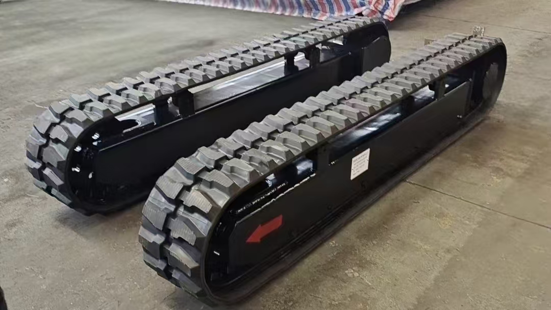
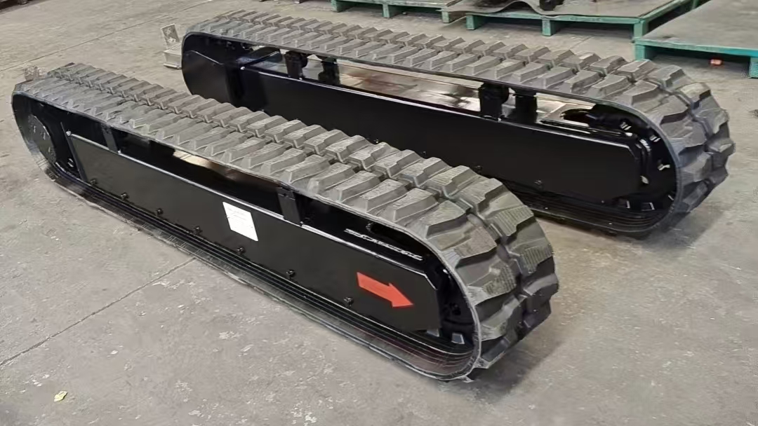
o Rubber crawler / combined rubber crawler: Suitable for small and medium-sized dredging machines, with light self-weight, no gold-gold wear on the crawler plate, and silt is less likely to get stuck.
o Open-hole steel crawler plate (drainage holes): The steel crawler plates need to have drainage/pressing holes in the middle to rely on the heavy wheels to squeeze out the silt.
2. Guide wheels and tensioning mechanism:
o Use large-stroke hydraulic tensioning/spring buffering devices. When underwater debris is sucked in, it can automatically retreat and buffer to prevent the crawler tensioning force from being too large and breaking the pin shaft.
o Add anti-skid guard plates (crawler guide plates): Full-length guide grooves are set on both sides of the chassis to prevent lateral skidding and skidding.
5. Underwater hydrodynamics and stability design
1. Center of gravity control:
o Underwater subjected to water flow buoyancy and water flow resistance, the center of gravity should be as low as possible.
o The front end of underwater dredging is often equipped with a cutter suction head or underwater digging bucket, and it is necessary to ensure that the rear part of the crawler does not lift its buttocks when operating at the front end (anti-overturning moment design).
2. Water Resistance and Anti-Skid Function:
o The chassis frame avoids the use of large-area flat water-blocking structures. Instead, it mostly adopts streamlined or frame-type penetration structures to reduce the water flow's thrust on the chassis.