 Phone:
 E-mail:


The problem of tracks detachment on the crawler chassis is indeed a headache, but it is a problem that can be effectively solved through systematic design and proper use. By optimizing the design and production processes in collaboration, as well as through correct usage and maintenance, the risk of tracks detachment can be significantly reduced.
First, identify the cause of the detachment.
- Failure of tensioning system: For instance, insufficient tension causes the tracks to become slack, or the tensioning device (such as bolts) loosens during vibration, directly leading to detachment.
- Excessive lateral slip: During sharp turns or when driving on slopes, the huge lateral force may cause the tracks to slide laterally off the bottom rollers or sprocket.
- Excessive wear of components: Wear of the pin shaft results in the track pitch "lengthening", or the wear of the supporting wheels reduces their guiding ability, eventually causing detachment.
- Foreign object intrusion: Stones or mud and sand getting stuck between the tracks and the guide wheels may cause deformation or an increase in gap, resulting in derailment.
Design Prevention: Establishing the Foundation for Anti-Relaxation Bands
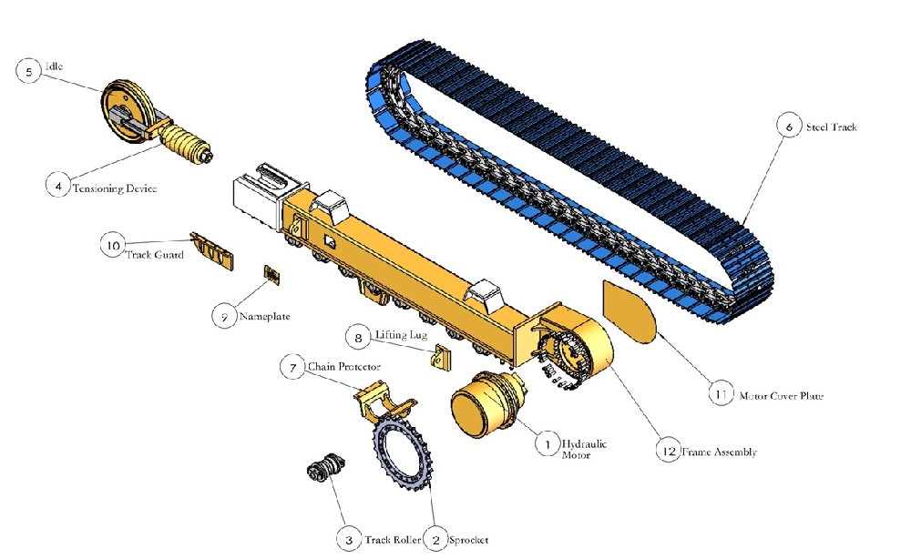
· Precise calculation and selection: Based on the vehicle weight, engine torque and maximum driving resistance, the specifications, pitch and matching of the chassis "four rollers and one track" are precisely calculated. During extreme conditions such as steering and climbing, simulation software is used for simulation and verification.
· Optimization of key details: Through active protection design, derailment can be inhibited at the source:
· Multi-parameter optimization of matching parameters: Through mechanical analysis and simulation, the geometric parameters of the sprockets, bottom rollers and front idlers are optimized to ensure correct meshing.
· Strengthening mechanical anti-loosening: Anti-loosening plates, limiters or fine-threaded screws are added to the tensioning bolts to prevent significant loosening caused by vibration.
· Upgrading adaptive/hydraulic tensioning: Using spring-loaded automatic or hydraulic tensioning devices, constant tension is maintained at all times. The double-idler design can also reduce stress.
· Nested "track" design: By setting a "concave-convex" cooperating structure between the track plate and the pulley, multiple tracks are formed, strongly restricting lateral slip.
· Adding lateral baffles: Install baffles higher than the track on both sides of the sprockets and front idlers to directly provide physical obstruction.
· Integrating mud scraping and drainage: Design drainage channels or mud scraping plates in key components to prevent hard objects from getting stuck and causing structural deformation.
· Coordinated vehicle system: Optimize the vehicle's center of gravity and weight distribution to avoid excessive local pressure and reduce the risk of abnormal wear of the track.
Manufacturing and Craftsmanship: Transforming Design into Reliable Reality
· Strictly control the quality of raw materials: strictly monitor the alloy composition, mechanical properties and wear resistance of the track steel and rollers steel. Optimize the rubber formula to enhance tear resistance and aging resistance, and increase the bonding strength with steel wires/iron teeth.
· Ensure the accuracy of key processes: Precision casting/forging: ensure the precise tooth profile of the sprocket and smooth meshing with the track.
· High-quality heat treatment: conduct heat treatment such as quenching on components like pins and sleeves to ensure surface hardness and wear resistance, while maintaining core toughness.
· Thorough cleaning and assembly: ensure that all components (especially hydraulic tensioning oil cylinders) are absolutely clean before assembly; strictly assemble and glue them firmly in accordance with specifications.
· Strengthen quality inspection: establish a full-process high-precision detection system from raw materials to finished products to ensure that component dimensions and positional tolerances are qualified. Conduct strict performance tests on the finished products.
· Introduce intelligence: implant sensors for tension force, track position, etc., and cooperate with the control system to achieve dynamic warning and automatic adjustment. Reserve interfaces and installation positions during manufacturing.
Through the systematic measures that link the design end and the production end closely together, most of the detachment problems can be basically prevented.
Apart from design and production, correct operation and maintenance by users during use are equally crucial. By following the following points, the risk of detachment can be significantly reduced.
Operating habit: Avoid causing detachment of the track
1. Smooth start and turning: Avoid making sharp turns or full-speed turns while stationary. Instead, make small, repeated, and gradual turns to reduce lateral thrust. Start slowly and accelerate gradually to prevent the tracks from slipping or twisting due to sudden large torque.
2. Control speed and terrain: Reduce speed on rough, gravel, or muddy surfaces. When driving at high speed and encountering obstacles or sharp turns, it is very likely to lose traction. Avoid driving for a long time on slopes that exceed the design limit of the chassis (usually < 30°).
3. Avoid overloading and collisions: Use strictly within the rated load capacity. When going up steep slopes or crossing ditches, face the direction of travel as much as possible to avoid excessive force on one side of the tracks or the bottom of the tracks being suspended. Never use the side of the tracks to collide with hard objects.
Daily Inspection and Maintenance: Preventing Problems Before They Occur
1. Before each operation:
· Tension check: Measure with a ruler. Standard reference: The deflection (flexure) of the middle part of the upper track should be approximately 2% to 3% of the distance between the two wheels. Loosening is prone to cause detachment, while tightness aggravates wear. Check for any leakage in the tensioning device (such as the grease cylinder).
· Foreign object removal: Remove stones, mud clumps, or iron wires that have become stuck between the driving wheel, guiding wheel, and supporting load wheel in a timely manner.
· Visual inspection: Check for cracks or deformations in the track plate and chain rail, and whether the pin shaft is loose or has shifted.
2. During operation: If you hear abnormal sounds (such as "clicking" metal friction sounds) or feel sudden jolts on one side, stop immediately for inspection. Do not force the vehicle to continue moving.
3. Regular maintenance and adjustment:
· Adjust tension by time: After the new track is used for 50-100 hours, it should be re-adjusted for tension (due to initial stretching). Then, check the tension once every 250-500 hours.
· Uniform wear management: Regularly switch the tracks left and right (if the design allows), which can balance the wear and prevent excessive slack on one side.
· Replace worn parts: Replace the assembly or segments when the chain track pitch elongates by more than 3%, the outer diameter of the pin sleeve wears down to 5% to 10% of the original size, or the rubber block is severely torn.
⚠️ Emergency Handling After Removing the Strap
If the track has come off, stop the vehicle immediately and strictly prohibit attempting to "rush back" by increasing the throttle. This is very likely to damage the drive gear teeth or break the tracks. Use a jack to lift the side where the belt has come off, clear the debris, and use tools such as a crowbar to reset it in the order of "first insert the drive wheel/guide wheel, then align the chain wheel". If you are not experienced, please have professional maintenance personnel handle it.
Overall, when using it, following the standard operating procedures (slow, gentle, stable) + conducting regular checks on tension and cleaning + replacing worn parts in a timely manner are the most effective methods for preventing the detachment of the belt at the user end.